

What Factors Cause Surface Roughness Variations in Machined Glass Fiber Filled PEEK Rods
2026-06-01
When precision machining Glass Fiber Filled PEEK Rods, manufacturers often encounter inconsistent surface finishes. Understanding the root causes of surface roughness variations is critical for industries such as aerospace, medical, and semiconductor manufacturing. Guangzhou Ideal has spent years analyzing these variables to help clients achieve superior machined surfaces from Glass Fiber Filled PEEK Rods.
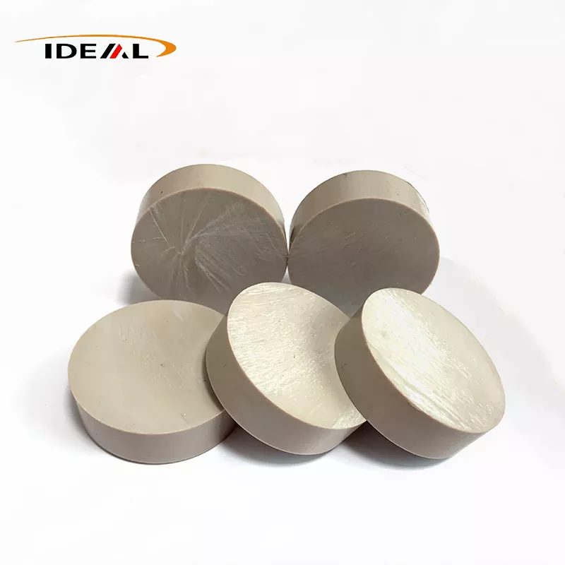
Key Factors Influencing Surface Roughness
The table below outlines the primary contributors to surface finish inconsistencies:
| Factor Category | Specific Variable | Impact on Surface Roughness |
|---|---|---|
| Tool Geometry | Rake angle, clearance angle | Improper angles cause fiber pullout |
| Cutting Parameters | Feed rate, spindle speed | High feed rates increase chatter marks |
| Material Properties | Glass fiber orientation | Random orientation creates micro-grooves |
| Cooling Method | Coolant type and flow | Insufficient cooling leads to thermal softening |
| Machine Rigidity | Spindle runout, tool holder condition | Vibration transfers to workpiece surface |
Detailed Mechanisms of Roughness Variation
Glass fiber content (typically 30% by weight) introduces abrasive characteristics. When machining Glass Fiber Filled PEEK Rods, fibers can be either cleanly sheared or pulled from the PEEK matrix. Pulled fibers leave voids that manifest as increased Ra values (average roughness). The following list highlights critical process-related causes:
-
Tool wear progression: As carbide or diamond tools dull, friction rises, generating heat that softens the PEEK matrix while fibers remain hard, leading to tear-out.
-
Chip evacuation: Poor chip removal allows machined particles to recut the surface, embedding glass fragments into the rod surface.
-
Clamping pressure: Excessive workpiece clamping distorts the rod during machining; when released, the surface relaxes unevenly.
Glass Fiber Filled PEEK Rods FAQ - Common Questions
What is the optimal feed rate for minimizing surface roughness when turning Glass Fiber Filled PEEK Rods
The optimal feed rate typically ranges from 0.05 to 0.15 mm/rev, depending on rod diameter and glass fiber percentage. Lower feed rates (0.05–0.08 mm/rev) produce finer finishes (Ra 0.4–0.8 µm) but risk excessive heat generation if dwell time increases. Higher feed rates above 0.15 mm/rev often create periodic tool marks and fiber pullout. Guangzhou Ideal recommends starting at 0.10 mm/rev with a cutting speed of 80–120 m/min using uncoated carbide tools. Always perform test passes and measure surface roughness with a profilometer to dial in exact parameters for your specific rod batch.
Does the cooling method significantly change surface finish on Glass Fiber Filled PEEK Rods
Yes, cooling method dramatically affects surface finish. Flood coolant with water-soluble oil (5–8% concentration) is superior to mist or dry cutting because it reduces frictional heat that softens the PEEK matrix. Without adequate cooling, the matrix smears over fiber ends, creating a deceptive smooth surface that actually hides subsurface damage. When that smeared layer is removed during cleaning or service, exposed fibers create a rough, abrasive surface. Through-tool coolant or high-pressure directional nozzles (minimum 15 bar) improve chip flush and maintain consistent thermal conditions. Guangzhou Ideal has documented Ra improvements from 1.6 µm to 0.6 µm simply by switching from mist to flood cooling on identical Glass Fiber Filled PEEK Rods.
How can I distinguish between tool-induced and material-induced roughness in Glass Fiber Filled PEEK Rods
Tool-induced roughness typically appears as periodic, evenly spaced marks matching spindle rotation or feed rate harmonics. These marks are usually parallel or helical along the machining direction. Material-induced roughness from glass fiber pullout appears random, with small craters or protruding fiber ends visible under 50x magnification. To isolate the cause, machine a rod from unfilled PEEK using identical parameters. If roughness disappears, the issue is glass fiber related. If roughness persists, examine tool wear, spindle bearings, or machine vibration. Guangzhou Ideal provides machinability testing services where we section your machined parts and analyze surface topography under SEM to precisely identify the source.
Best Practices for Consistent Finishes
Guangzhou Ideal recommends using polycrystalline diamond (PCD) tools with positive rake angles (+5° to +8°) specifically ground for fiber-reinforced polymers. Maintain tool replacement intervals at every 200–300 linear meters of machined rod length. Implement real-time surface monitoring with laser profilometers to detect roughness shifts before parts fall out of tolerance.
Contact Us
For expert guidance on machining Glass Fiber Filled PEEK Rods or to request custom-sized rods with certified surface finish specifications, contact Guangzhou Ideal today. Our engineering team provides process optimization support and sample machining trials to verify your surface quality requirements. Reach out via our website or email to discuss your application.